ISSN : 2349-3917
American Journal of Computer Science and Information Technology
Visually-Guided Robotic Machining of Complex Components
1State key Laboratory of Digital Manufacturing Equipment and Technology, Huazhong University of Science and Technology, Wuhan, China
2Hubei Key Laboratory of Advanced Technology for Automotive Components, Wuhan University of Technology, Wuhan, China
*Corresponding Author:
Wen-long Li
State Key Laboratory of Digital Manufacturing Equipment and Technology
Huazhong University of Science and Technology
Wuhan, China
E-mail: wlli@mail.hust.edu.cn
Received Date: September 2, 2020; Accepted Date: September 17, 2020; Published Date: September 28, 2020
Citation: Li WL, Zhu D (2020) Visually-Guided Robotic Machining of Complex Componenfts. Am J Compt Sci Inform Technol. Vol.8 No.3:58
Abstract
In this paper, we review a thought experiment in statistical thermodynamics leading to the foundation of the field of Physical Informatics. We discuss the basic concepts of Physical Informatics, such as Information Entropy and Information Energy. Then we apply the aforementioned concepts in the analysis of a system of N identical non-interacting particles in n dimensions to verify the Entropic Uncertainty Relation (EUR) in 3 dimensions and establish EUR for 1 and 2 dimensions.
Keywords
Robotic machining; Turbine blade; Measurement; Point cloud matching
Background
The role of industrial robots is changing from manipulators to skillful machining robots (Figure 1).
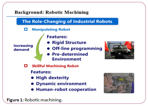
Figure 1: Robotic machining.
The most important characteristic of Robotic Machining is Integration of Measurement-Machining-Manipulating (3 M) (Figure 2).
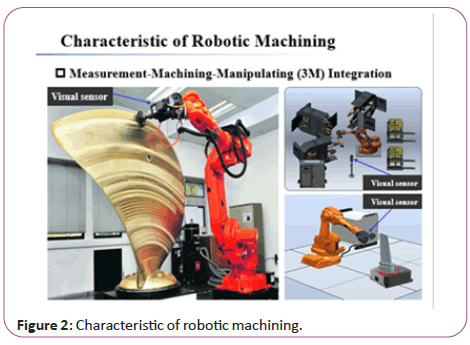
Figure 2: Characteristic of robotic machining.
Methodology
Challenges of robotic machining
The key problem in robotic machining is how to control of the dynamical Robot-Processing Interaction behaviors. It concerns kinematic modeling, dynamic modeling, on-site measurement, and control of the machining process [1] (Figure 3).
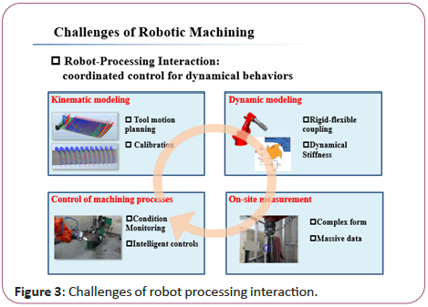
Figure 3: Challenges of robot processing interaction.
In the application of robot grinding, there are several hardware/ software systems, such as robot basis/end systems (used to generate spatial operation), tool system (used to grind the work piece), laser scanner system (used to scanning the work piece and localize the work piece with suitable allowance), and design model system (used to programme the grinding path). It is a challenge task to calibrate them in a fast, accurate and economic manner. Specially, the hand (robot) eye (scanner) calibration and shape matching [2] (between measured points and the CAD model) is two important tasks, directly determining the final shape accuracy of blade grinding (Figure 4).
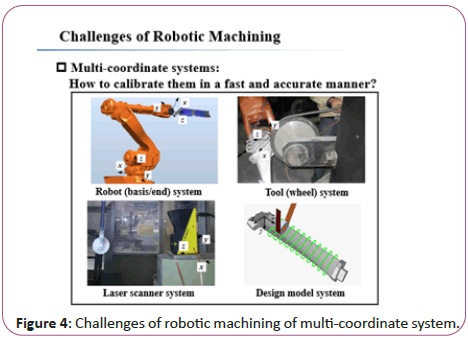
Figure 4: Challenges of robotic machining of multi-coordinate system.
During on-site scanning measurement, the data scale is large (such as 10 thousands/million), and there usually exists uneven density data/noise data/missing regions due to the complexity of blade [3]. In addition, the initial pose of the objects required to be matched is arbitrary. The measured points are represented in scanning coordinate system, and the design model is represented in design coordinate system [4]. Consider the concave-convex characteristic, the suction surface and pressure surface of blade should be set as different grinding allowances, for obtaining a relatively stable grinding force. How to implement accurate shape matching and provide suitable grinding allowances under measuring defects is a challenging task [5] (Figure 5).
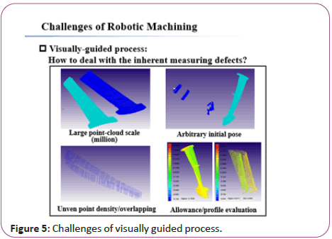
Figure 5: Challenges of visually guided process.
In recent years, some research institutions have begun to study the robot inspection technique or optical inspection technique. After the blade is scanned, one important task is to calculate the inspection parameters (such as mean line/maximum gauge/ tortuosity). Of course, during on-site inspection by the worker, the integration of sensor-algorithm-software is quite required, in order to save time/cost and improve automation operation [6] (Figure 6).

Figure 6: Challenges of robotic optical inspection.
Measurement
In grinding application, usually a laser tracker is used to calibrate the 24 joint parameters of robot. However, buying a laser tracker is expensive (about 2 million RMB), and it is hard to transport and operate since the laser tracker is very heavy. In our method, a mathematical model of 30 calibration parameters (24 joint parameters and 6 pose parameters) is built and solved, for fast obtaining the pose calibration from hand system {E} to scanner system {S}. In the model, part 1 denotes the rigid frame from basis system {B} to scanner system {S}, and part 2 denotes the moving joint frame from the basis system {B} to the system {E}. The main advantage of the proposed method is that it is simple and economic since just a standard sphere is used to implement the calibration process [7] (Figure 7).
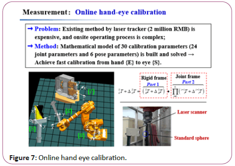
Figure 7: Online hand eye calibration.
Due to the surface complexity and clamping uncertainty, the Traditional Matching Algorithm (ICP) may be trapped into a wrong local optimal value. It leads to large allowance region (causing high grinding force and vibration) and small/no allowance region (causing empty grinding). To address this problem, an Adaptive Distance Function (ADF) is defined as a new metric to guarantee convergent speed and stability during matching. The basic novelty is that the ADF use normal distance and partial tangential distance to construct the objective function of shape matching, in order to balance the convergent speed and convergent stability [8] (Figure 8).
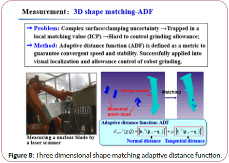
Figure 8: Three dimensional shape matching adaptive distance function.
To address this problem, an Adaptive Distance Function (ADF) is defined as a new metric to guarantee convergent speed and stability during matching. The basic novelty is that the ADF use normal distance and partial tangential distance to construct the objective function of shape matching, in order to balance the convergent speed and convergent stability [9].
Results
Traditional methods (ICP/TDM) are based on squared distance minimization, there are 3 disadvantages; 1) The point cloud is matched with the design model under minimized distance deviation, regardless of different allowance requirements for suction surface and pressure surface; 2) The matching result is prone to just meet with high density regions, since the measured points in these regions play a leading roles; 3) The squared operation accelerates this wrong tendency [10].
Note that the variance describes the deviation degree between every sample value and its mean value. By subtracting the mean value of distance deviation di, the variance minimization can balance the contributions of all measured points when iteratively matched with the design model, and weaken the influence of square operation for high density points. Stable matching with required grinding allowances is obtained (Figure 9).
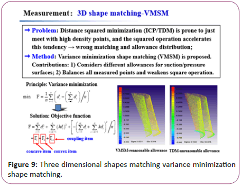
Figure 9: Three dimensional shapes matching variance minimization shape matching.
To address the problem of large-scale data from laser scanning, we propose a curvature-adaptivity simplification method for blade features, where the space division and octree encoding are used. After simplification, this method can fine keep the blade high-curvature features such as leading/trailing edges, rabbet and lug boss [11] (Figure 10).
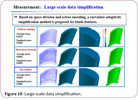
Figure 10: Large scale data simplification.
Due to the scanning uncertainty, there usually exists Gaussian noise in point cloud, and the fairing implementation is a double- edged sword. The integral volume of the point cloud will be compressed after fairing. If efficient fairing is carried out, the noise is smoothed but required features remains; otherwise, some vital features disappear [12].
Therefore, we defined the density entropy of point cloud, used to calculate fairing factor and preserving factor (for alpha) in each fairing step. This will better preserve blade’s high-curvature features such as leading/trailing edges, meanwhile fairing the point cloud (Figure 11).
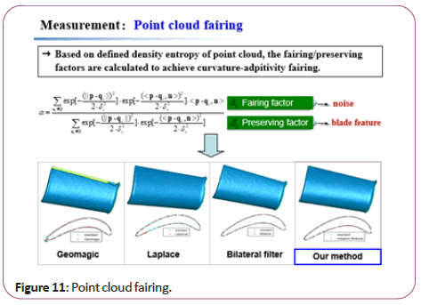
Figure 11: Point cloud fairing.
According to the scanned discrete point cloud of blade, we systematically investigates the calculation methods of single section parameters [13,14] (such as mean camber line, maximum gauge, chord length, chord inclination, center points of leading/ trailing edges), and the multi-section parameters (such as tortuosity, skewness, profile error) (Figure 12).
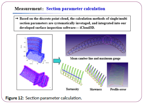
Figure 12: Section parameter calculation.
In the applications of visual localization during robot grinding, blade inspection and transformation correction, there exists a common problem: commercial software (Geomagic) lacks specific functionality (such as stable ADF/VMSM matching, fast calculation of transverse/lengthways moving, integration of scanning sensor-calculation method-unified software interface), and it has to use multi commercial software with trivial human- computer interaction (Figures 13-17).
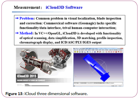
Figure 13: iCloud three dimensional software.
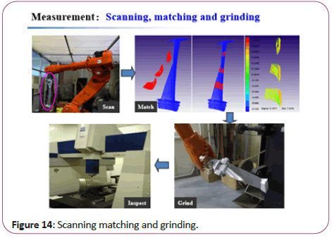
Figure 14: Scanning matching and grinding.
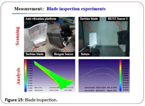
Figure 15: Blade inspection.
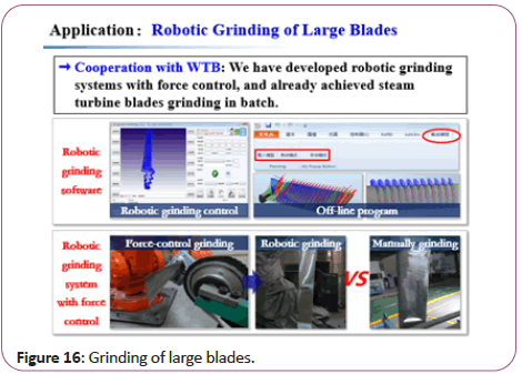
Figure 16: Grinding of large blades.
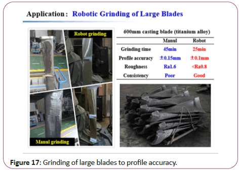
Figure 17: Grinding of large blades to profile accuracy.
Discussion and Conclusion
We cooperated with WTB Company and have developed the robotic belt grinding system with force control, and already achieved steam turbine blades grinding in batch. Particularly for the 600 mm length casting blade, compared with the grinding time, profile accuracy and surface roughness Ra by manual operation, the corresponding values are reduced to 25 min, ± 0.1 mm, <0.8 μm by robotic grinding respectively.
Application
Based on the VC++/OpenGL platform, we developed special software mainly used for above application. It has the functionality of optical scanning, data simplification, 3-D matching, profile inspection, parameter calculation, chromatograph display, ICD/ ASC/PLY/IGES output, and so on
This is the main process of visually-guided robotic belt grinding.
This is the blade inspection experiments, using the scanning sensor and proposed calculation methods.
References
- Xie H, Li WL, Yin ZP, Ding H (2019) Variance minimization iterative matching method for free form surfaces-Part II: Experiment and analysis. IEEE Transactions on Automation Science and Engineering 16: 1192-1204.
- Xie H, Li WL, Yin ZP, Ding H (2019) Variance minimization iterative matching method for free form surfaces-Part I: Theory and method. IEEE Transactions on Automation Science and Engineering 16: 1181-1191.
- Wang G, Li WL, Rao F, He ZR, Yin ZP (2018) Multi-parameter optimization of machining impeller surface based on the on-machine measuring technique. chin j aero 32: 2000-2008.
- Wang G, Li WL, Tong G, Pang CT (2017) Improving the machining accuracy of thin-walled parts by online measuring and allowance compensation. Int J Adv Manuf Technol 92: 2755-2763.
- Li WL, Wu A, Li ZC, Zhang G, Yu WY (2017) A new calibration method between an optical sensor and a rotating platform in turbine blade inspection. Meas Sci Technol 28: 035009.
- Li WL, Wang G, Zhang G, Li QD, Yin ZP (2017) Interference-free inspection path generation for impeller blades using an on-machine probe. IEEE/ASME Transactions on Mechatronics 22: 1218-1226.
- Li WL, Xie H, Zhang G, Yan SJ, Yin ZP (2016) 3-D shape matching of a blade surface in robotic grinding applications. IEEE/ASME Transactions on Mechatronics 21: 2294-2306.
- Li WL, Xie H, Zhang G, Li QD, Yin ZP (2016) Adaptive bilateral smoothing for a point-sampled blade surface. IEEE/ASME Transactions on Mechatronics 21: 2805-2816.
- Zhu D, Feng X, Xu X, Yang Z, Li W (2020) Robotic grinding of complex components: A step towards efficient and intelligent machining–challenges, solutions, and applications. Robotics and Computer-Integrated Manufacturing 65: 101908.
- Lv Y, Peng Z, Qu C, Zhu D (2020) An adaptive trajectory planning algorithm for robotic belt grinding of blade leading and trailing edges based on material removal profile model. Robotics and Computer-Integrated Manufacturing 66: 101987.
- Xu X, Zhu D, Wang J, Yan S, Ding H (2018) Calibration and accuracy analysis of robotic belt grinding system using the ruby probe and criteria sphere. Robotics and Computer-Integrated Manufacturing 51:189-201.
- Zhu D, Luo S, Yang L, Chen W, Yan S (2015) On energetic assessment of cutting mechanisms in robot-assisted belt grinding of titanium alloys. Trib Int 90: 55-59.
- Zhu D, Xu X, Yang Z, Zhuang K, Yan S et al. (2018) Analysis and assessment of robotic belt grinding mechanisms by force modeling and force control experiments. Trib Int 120: 93-98.
- Xu X, Zhu D, Zhang H, Yan S, Ding H (2017) TCP-based calibration in robot-assisted belt grinding of aero-engine blades using scanner measurements. Int J Adv Manuf Technol 90: 635-647.

Open Access Journals
- Aquaculture & Veterinary Science
- Chemistry & Chemical Sciences
- Clinical Sciences
- Engineering
- General Science
- Genetics & Molecular Biology
- Health Care & Nursing
- Immunology & Microbiology
- Materials Science
- Mathematics & Physics
- Medical Sciences
- Neurology & Psychiatry
- Oncology & Cancer Science
- Pharmaceutical Sciences
