ISSN : 2576-392X
Dentistry and Craniofacial Research
Condylar Movement Assessment is Severe Attrition Patient Undergoing Orthodontic Treatment: Joint Vibrant Analysis Procedure
Private Practice limited to Orthodontics and TMD, Odessa, Ukraine
- *Corresponding Author:
- Koval S
Private Practice Limited to Orthodontics and TMD, Odessa, Ukraine
Tel: 00380933690947
E-mail: sve.koval@icloud.com
Received date: November 04, 2016; Accepted date: December 05, 2016; Published date: December 10, 2016
Citation: Koval S. Condylar Movement Assessment is Severe Attrition Patient Undergoing Orthodontic Treatment: Joint Vibrant Analysis Procedure. J Anim Res Nutr. 2016 1:1. doi: 10.21767/2576-392X.100004
Abstract
Orthodontic treatment of the patient with severe teeth attrition was performed with the provisional restorations to recover occlusal vertical dimension. The increase in VDO causes posterior mandibular rotation and the increase in overjet. The overjet correction is one of the main goals of the orthodontic treatment in these patients. The anterior mandibular position was obtained at the end of orthodontic treatment. Condylar positions were assessed immediately after the bite raising procedure and after the completion of treatment. Both CBCTs of the temporomandibular joints and the Joint vibration analysis (JVA) were performed. Coronal views of the CBCTs of TMJs and zoomed vibration views of the JVA of TMJs are essential in assessment of the condylar instability.
Keywords
Attrition; Orthodontic treatment; Occlusal vertical dimension; Condylar position; Joint vibrant analysis
Introduction
Cases with severe attrition present challenge to orthodontist as are related to a loss of the occlusal vertical dimension (VDO) [1]. Attrition is the wearing away of a tooth as a result of tooth-totooth contact, as in mastication, occurring only on the occlusal, incisal, and proximal surfaces [2]. Teeth with severe attrition are subject to restorative treatment. Space necessary for the teeth height gain is obtained from the increasing of the occlusal vertical dimension [3].
The latter is obtained via mandible posterior rotation [4]. The rotation hinge axis for the mandible is the center of the condyle head [4]. With posterior mandible rotation, the lower facial height increases and the overjet is increased either [5]. Overjet correction is one of the goals of the orthodontic treatment in these patients.
Various techniques are used to assess the condylar position in CBCT images of temporomandibular joints [6,7], emphasizing the sagittal and axial views as the main point. The condylar position obtained in sagittal and axial views are measured with little regard to the coronal view. The most results suggest that, Class I and Class III patients exhibit superior-anterior position of the condylar head as viewed in the sagittal cross-sections and posterior-superior position in Class II patients [7,8].
Functional evaluation of the opening-closing movement of the condyle heads in TMJs is necessary to observe. Different techniques are used for this purpose, among them computerized axiography [9], ultrasonic jaw-tracking devices for sagittal condylar inclination [10] and others.
The implementation of the joint vibrant analysis system was described by different practitioners as an effective tool for the non-invasive preliminary assessment of the internal TM joint derangements [11].
The aim of this article is to present the case of practical implementation of the joint vibrant analysis procedure in TM joint of the patient undergoing orthodontic treatment.
Case Description, Diagnosis and Treatment Planning
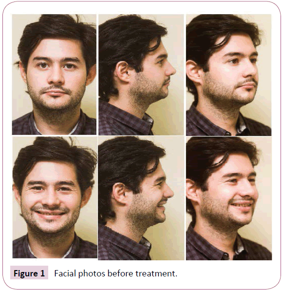
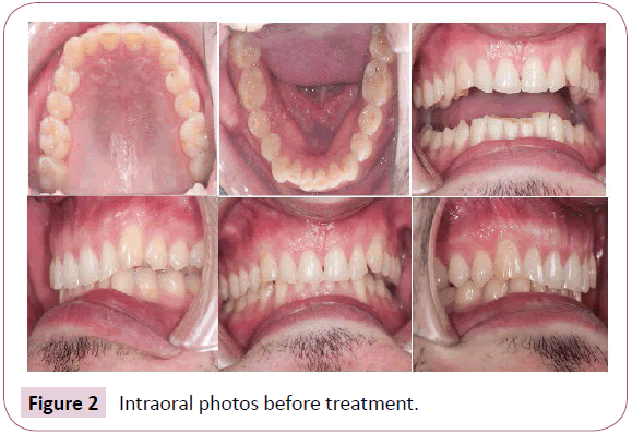
Male patient 27 years (Figure 1) was referred by a general dentist to undergo orthodontic treatment before permanent restoration of the severely worn teeth (Figure 2).
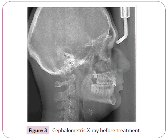
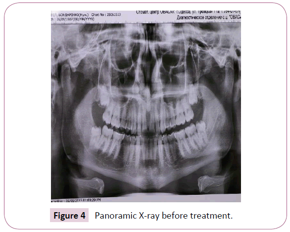
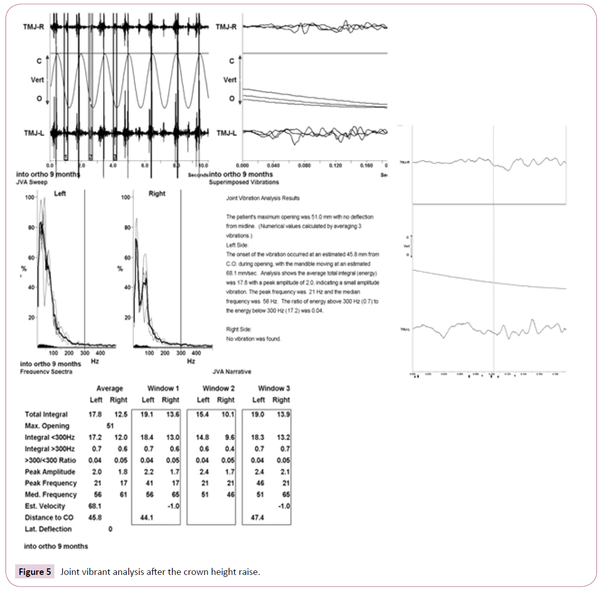
The examination protocol included: clinical examination, muscle and joint palpation, models mounted in the articulator assessment, CBCT of the TMJ, lateral cephalomentic (Figure 3) and panoramic X-rays (Figure 4) and joint vibrant analysis of the temporomandibular joints (JVA, Bioresearch, Milwaukee, USA) (Figure 5).
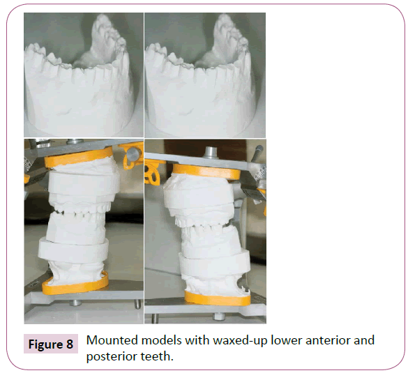
The initial procedure was to restore the lower incisor crown heights. The wax-up for remodeling of the lower incisor height was done by the orthodontic lab technician. The upper model was mounted into the articulator SAM 3 (SAM, Munich, Germany) according to the face bow recording of the upper jaw position in the patient. The bite registration was taken in the centric occlusion. The articulator pin was raised by the distance necessary to obtain adequate lower incisor height as established by the esthetic goal. The pin was raised by 5 mm. After the incisors were restored on the model in white wax, the canines and the posteriors were also restored according to the flat occlusal plane in the lower jaw (Figure 6).
The indirect temporary restorations were made with the composite (Filtek flowable, 3M ESPE, USA), put into the transparent tray. The tray was made on the wax-up model with the use of pressure-molding technique (Erkopress, Germany). After the restorations were put in place the CBCT of the TMJs was made as well as the Joint Vibration Analysis procedure.
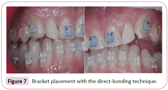
After placing the indirect temporary restorations braces with the 0.022 slot and Roth prescription (Ispire Ice, ORMCO, USA) were bonded with the use of direct-bonding technique (Figure 7).
The wire sequence included 0.014 NiTi coated upper and lower, 0.016 × 0.022 NiTi coated upper and lower, 0.016 × 0.022 ss upper and lower, 0.017 × 0.025 ss with U-shaped loops distal to lateral incisors on the upper and 0.017 × 0.025 ss without loops on the lower. The detailing wires were 0.016 NiTi on both arches. Class II elastics (170 g, 3/16’’, 3M Unitek) were added at the stage of 0.017 × 0.025 ss wires upper and lower. The elastic wear was aimed to place the mandible anteriorly and to reshape the upper dental arch through the force applied to the U-shaped loops on the upper wire (Figure 8).
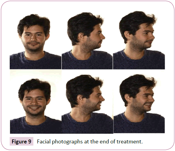
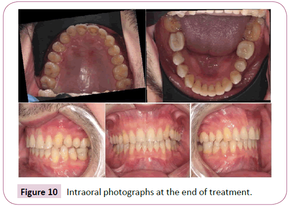
The treatment was accomplished in 11.5 months. The final facial and intraoral photographs are shown in Figures 9 and 10.
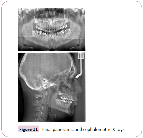
At the end of treatment before debonding the panoramic and cephalometric X-rays (Figure 11) were taken and the CBCT of the TMJs also assessed.
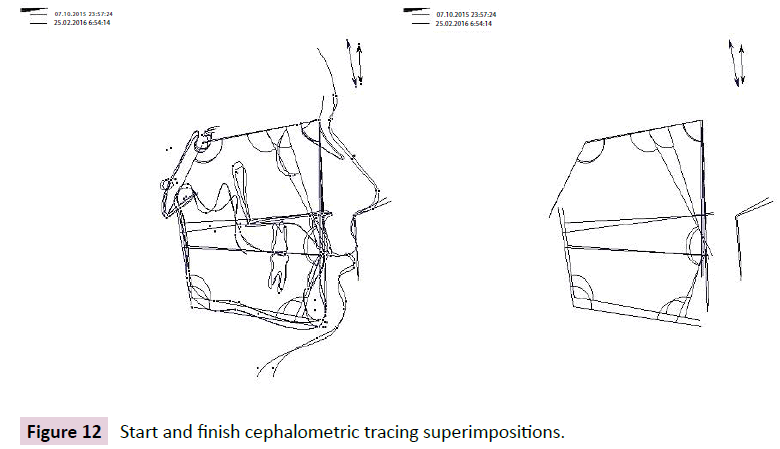
The superimposition tracings of the start and finish cephalometric X-rays are shown in Figure 12.
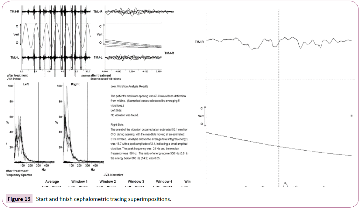
Joint vibrant analysis measuring was taken at the completion of orthodontic treatment and the results are presented in Figure 13.
Discussion and Results
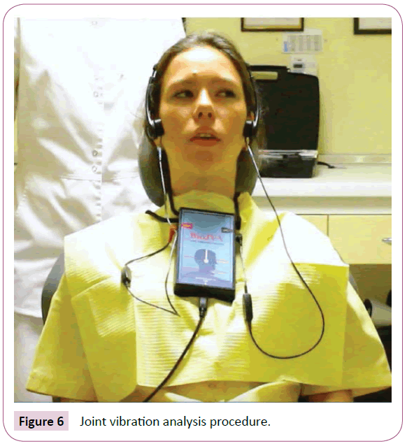
Joint vibrant analysis procedure is a non-invasive temporomandibular joint sound processing. The sound accelerometers are placed on the skin surface of a patient in the area of the lateral poles of mandibular condyles with the mandible in the maximum opening position. Accelerometers transfer the joint sounds into the program software (Figure 6).
The program software measures the vibrations in each joint and makes a numerical assessment of the vibration amplitude in Pascals. There are typical waveform patterns seen in Joint Vibration analysis, which correspond to different internal derangements. The patient`s vibration pattern (Figures 5 and 13) indicates condylar head instability. Patient`s records also show low amplitude vibrations; the origin of vibrations is localized in the left TMJ, the maximum jaw opening is measured as 51 mm. Post-treatment JVA data indicates the presence of the same type low amplitude vibrations with no change to the vibration values (Figure 13).
Monitoring condylar position both with joint vibrant analysis and the CBCT scans enables clinician to control condylar head position during the occlusion modification treatment, as stated earlier.
Combining joint vibrant analysis zoomed vibrations view with the coronal and sagittal views of joint CBCTs is a way of controlling of the condylar head stability in patients undergoing changes of VDO and orthodontic treatment.
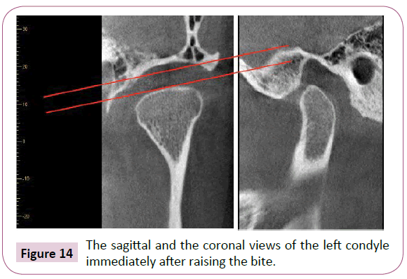
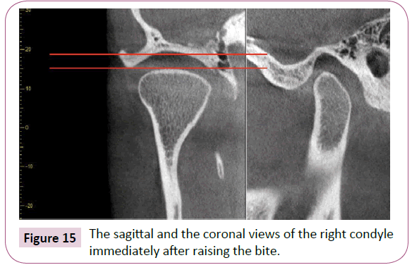
The raising of the bite was monitored by the CBCT scanning of the TMJs. The immediate CBCT scan of the TM Joints after the bite raising procedure was made. The sagittal and coronal views are shown in Figure 14 (left) and Figure 15 (right).
Several parameters were assessed. Among them: the shape and the dimensions of the condylar head, the cortical bone contour of the condylar head. The coronal view is extremely important to control mesio-lateral condylar head position and to assess its mechanical stability. The sagittal view is necessary to assess the mesio-distal condylar head position and the space between the condylar fossa, articular eminence, and the condyle head. The initial after-raising the bite scans show non-similar internal dimensions in both joints. The increased vertical dimension in the left joint on both views is associated with the more anterior position of the condyle head.
Immediately after placing the indirect restorations on the posterior teeth the occlusal adjustment procedure was made to control the transversal position of the mandible. The criteria for the correct transversal position of the mandible was the coincidence of the upper and lower midlines.
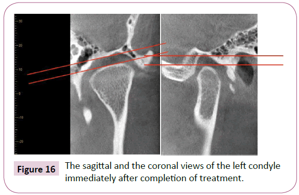
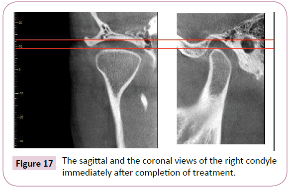
The final CBCT scans of both TMJs were made immediately after the completion of treatment. The sagittal and the coronal views of both condyles are shown in Figures 16 and 17.
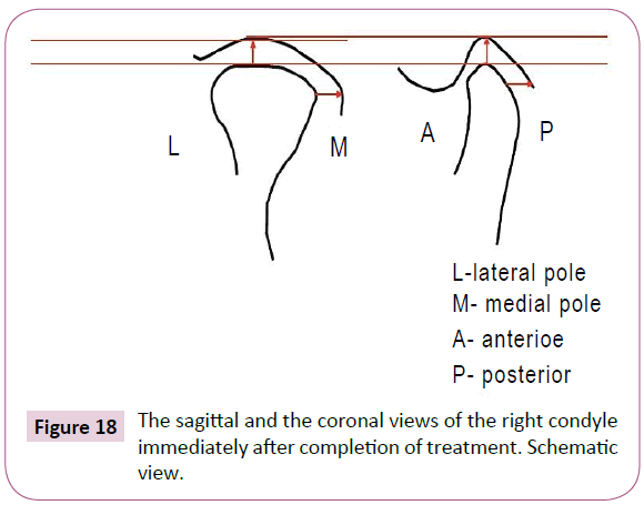
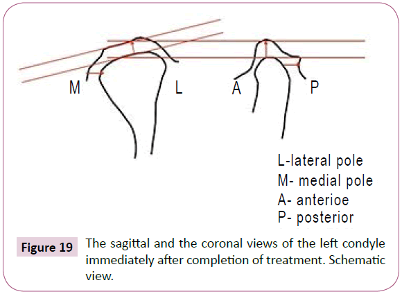
The dimensions between condyle head, articular eminence and the articular fossa were established similar at the end of orthodontic treatment. Schematic views of both condyles with relative dimensions are shown in Figures 18 and 19.
Conclusion
Patients undergoing changes in VDO and orthodontic treatment are prone to exhibit TMJ condylar head instability. These findings can be non-invasively assessed with the help of the joint vibrant analysis and confirmed by the coronal views of the TMJ CBCTs.
References
- Milosevic A, Burnside G (2016) The survival of direct composite restorations in the management of severe tooth wear including attrition and erosion: A prospective 8-year study. J Dent 44: 13-19.
- Jablonski S (1992) Jablonsky dictionary of dentistry. Malabar, Fla: Krieger Pub.
- Fradeani M, Barducci G, Bacherini L (2016) Esthetic rehabilitation of a worn dentition with a minimally invasive prosthetic procedure (MIPP). Int J Esthet Dent 11: 16-35.
- Paeng JY, Lee JH, Lee JH, Kim MJ (2007) Condyle as the point of rotation for 3-D planning of distraction osteogenesis for hemifacial microsomia. J Craniomaxillofac Surg 35: 91-102.
- Harari D, Redlich M, Miri S, Hamud T, Gross M (2010) The effect of mouth breathing versus nasal breathing on dentofacial and craniofacial development in orthodontic patients. Laryngoscope 120: 2089-2093.
- Paknahad M, Shahidi S, Iranpour S, Mirhadi S, Paknahad M (2015) Cone-beam computed tomographic assessment of mandibular condylar position in patients with temporomandibular joint dysfunction and in healthy subjects. Int J Dent 301796.
- Coskuner HG, Ciger S (2015) Three-dimensional assessment of the temporomandibular joint and mandibular dimensions after early correction of the maxillary arch form in patients with Class II division 1 or division 2 malocclusion. Korean J Orthod 45: 121-129.
- Kaur A, Natt AS, Mehra SK, Maheshwari K, Singh G, et al. (2016) Improved visualization and assessment of condylar position in the glenoid fossa for different occlusions: A CBCT Study. J Contemp Dent Pract 17: 679-686.
- Botos AM, Mesaros AS, Zimbran AI (2016) The contribution of computerized axiography to the functional evaluation of the temporomandibular joint: a case report. Clujul Med 89: 438-442.
- Cimic S, Simunkovic SK, Kocijan SS, Matijevic J, Dulcic N, et al. (2015) Articulator-related registration and analysis of sagittal condylar inclination. Acta Clin Croat 54: 432-437.
- Owen AH (1996) Rationale and utilization of temporomandibular joint vibration analysis in an orthopedic practice. Cranio 14: 139-153.
Open Access Journals
- Aquaculture & Veterinary Science
- Chemistry & Chemical Sciences
- Clinical Sciences
- Engineering
- General Science
- Genetics & Molecular Biology
- Health Care & Nursing
- Immunology & Microbiology
- Materials Science
- Mathematics & Physics
- Medical Sciences
- Neurology & Psychiatry
- Oncology & Cancer Science
- Pharmaceutical Sciences
